What is Strecs3D?
Strecs3D is a pre-processor designed to optimize 3D printing infill structures.
While standard 3D printing generates a uniform infill density throughout the entire model, Strecs3D uses stress analysis to automatically assign dense infill to areas under high load and sparse infill to low-stress areas.
Key Features
- Slicer Pre-processor: It sits between your CAD data and the slicer, adding manufacturing intelligence to your models.
- Fully Integrated Analysis: In ver 2.0.0, the stress analysis functionality—which previously relied on external software like Fusion 360 or FreeCAD—is now built directly into the app. You can complete the entire workflow within Strecs3D.
- 3MF Integration: It exports the analysis results as a 3MF file containing information on "which regions should have what percentage of infill," which can be seamlessly passed to major slicers.
GitHub: https://github.com/tomohiron907/Strecs3D


Official Website: strecs3d.xyz
Installation
- Download the appropriate installer for your OS (Windows / macOS) from the download link on the official website: strecs3d.xyz.
- Run the installer and launch the application.
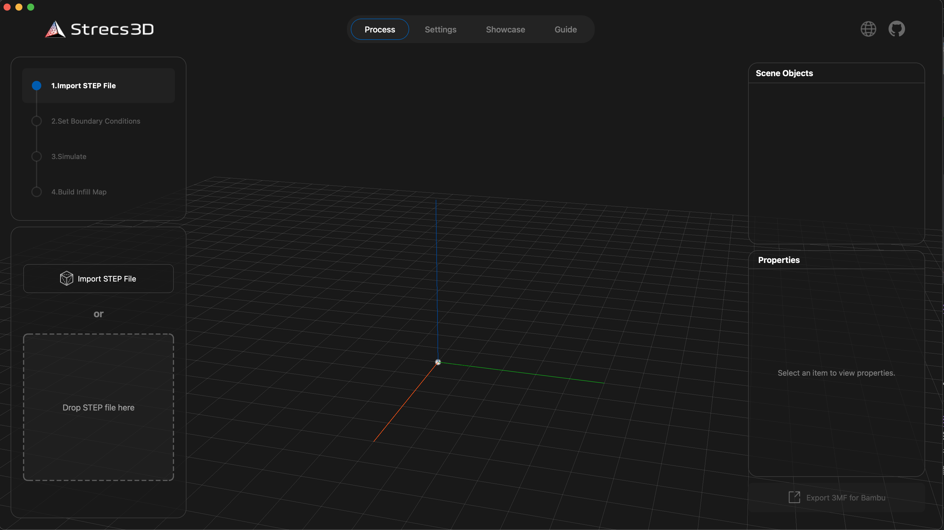
- Once the main screen appears, you are ready to go.
Basic Workflow
Using Strecs3D consists of four main steps: "Data Preparation," "Setting Analysis Conditions," "Simulation," and "Infill Map Generation."
1. Preparing CAD Data (STEP File)
While STL files are common in 3D printing, Strecs3D requires STEP files to perform precise structural analysis.
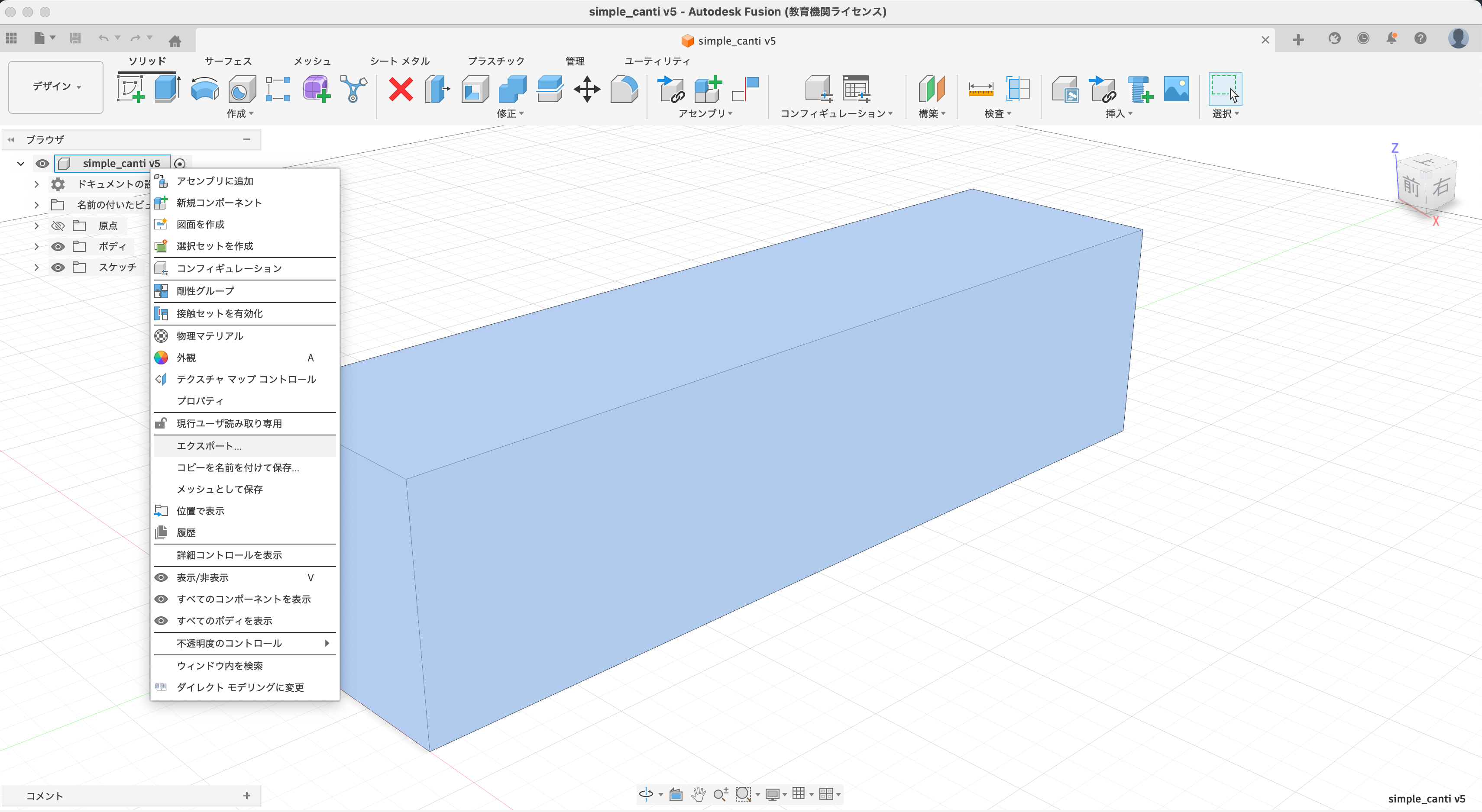
Example for Fusion 360: Right-click the top-level component in the Browser > [Export] > Select [STEP file] as the type and export.
Once you load the STEP file into Strecs3D, it will be displayed as follows:
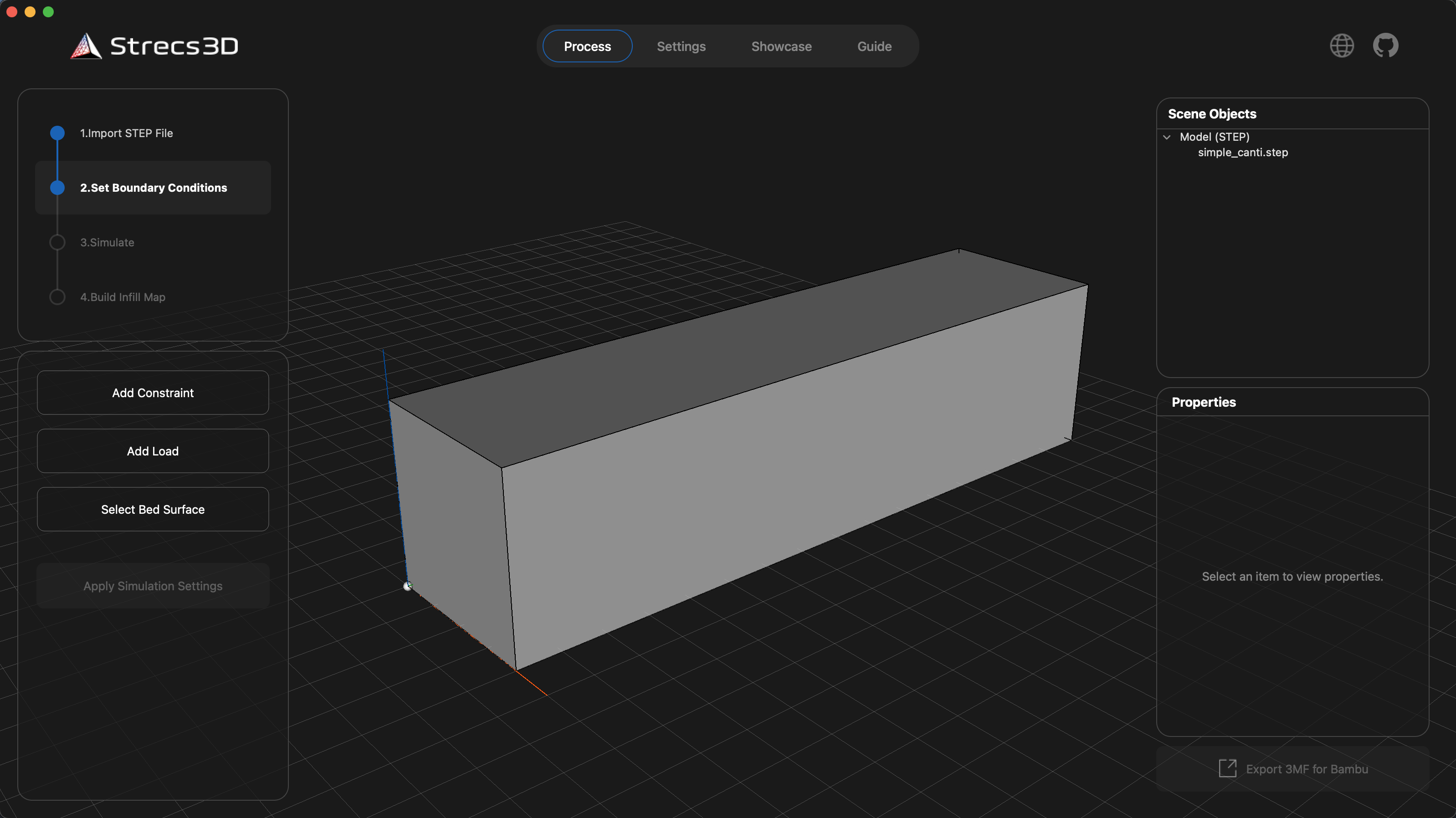
2. Setting Analysis Conditions
Load the STEP file into Strecs3D and define the constraints (fixed points) and loads (where force is applied). In this example, we use a cantilever beam (fixed on the left, load applied from the top).
-
Constraints (Add Constraint): Click the button and double-click the face you want to fix. A green cube will appear to indicate a successful constraint.
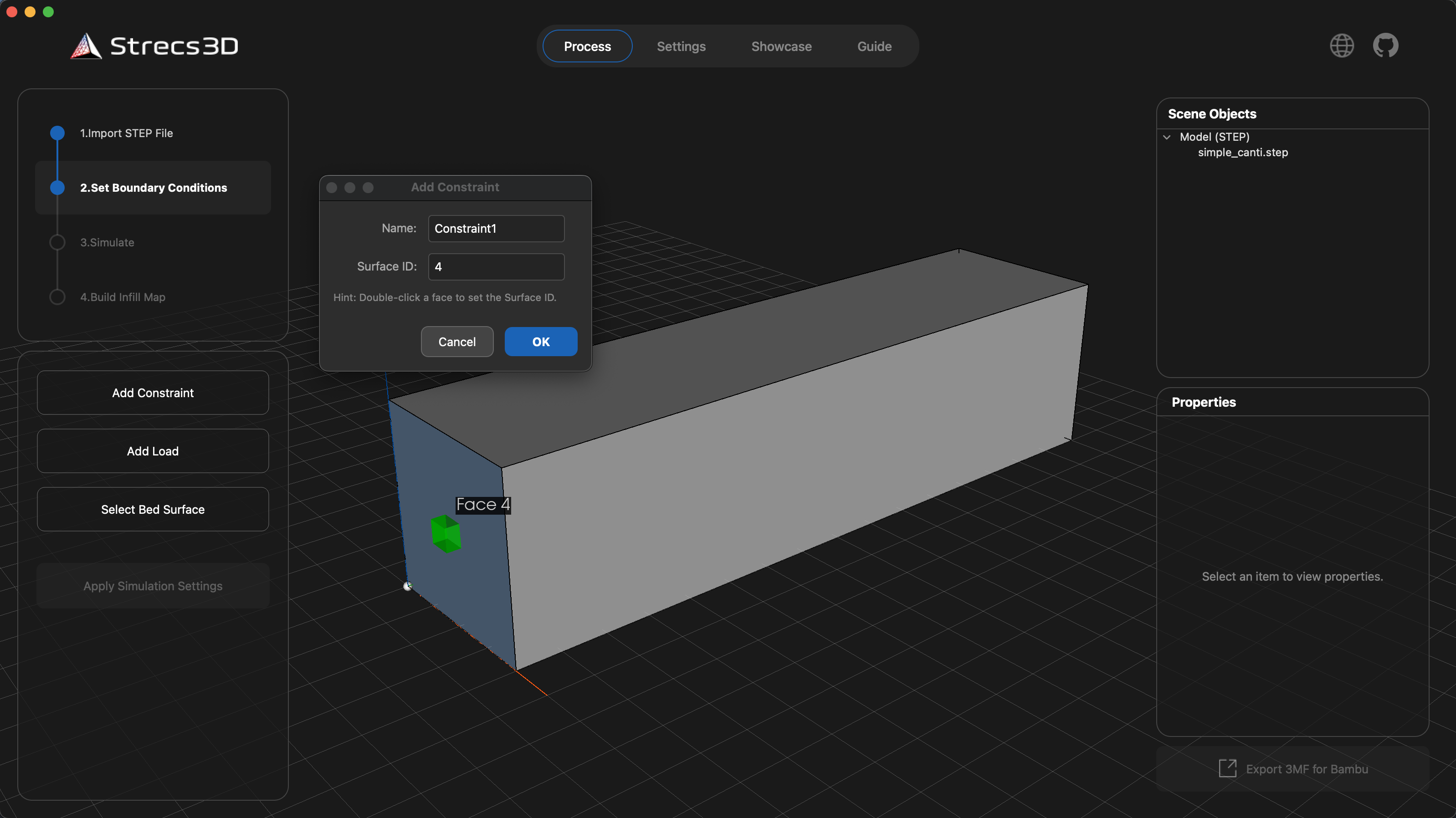
-
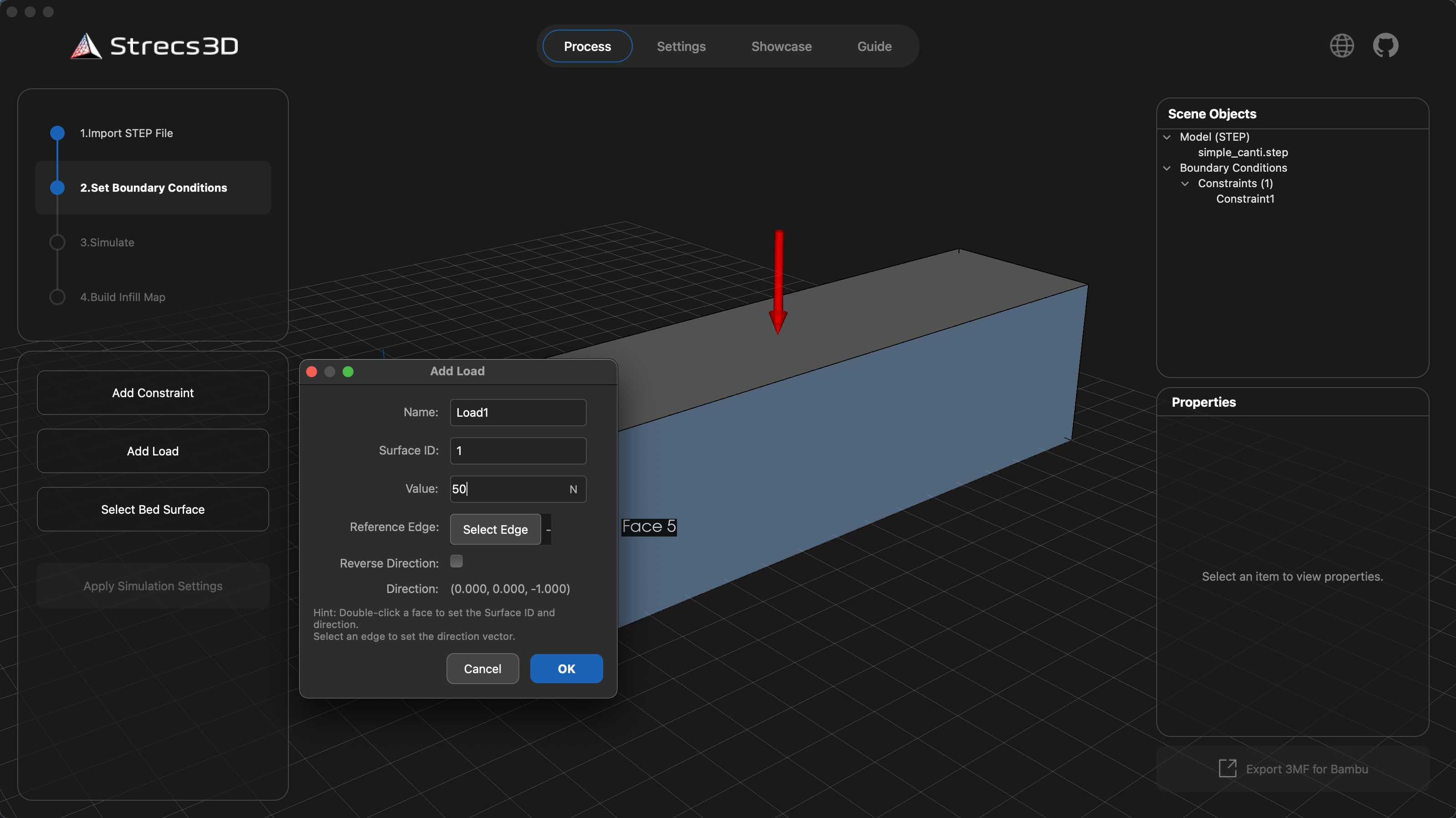
Loads (Add Load): Click the button and double-click the face where the load is applied. The direction of the force is shown with red arrows.
- Tip: Use the "Reference Edge" button to select an edge and adjust the force direction as needed.
- In this case, we are simulating a 50N downward load.
-
Print Orientation (Select Bed Surface): Since 3D prints are weaker against forces that cause delamination (layer splitting), you must specify the print orientation for the simulation. Click "Select Bed Surface," double-click the face that will touch the heatbed, and click
Apply. The model will rotate so that face is at the bottom.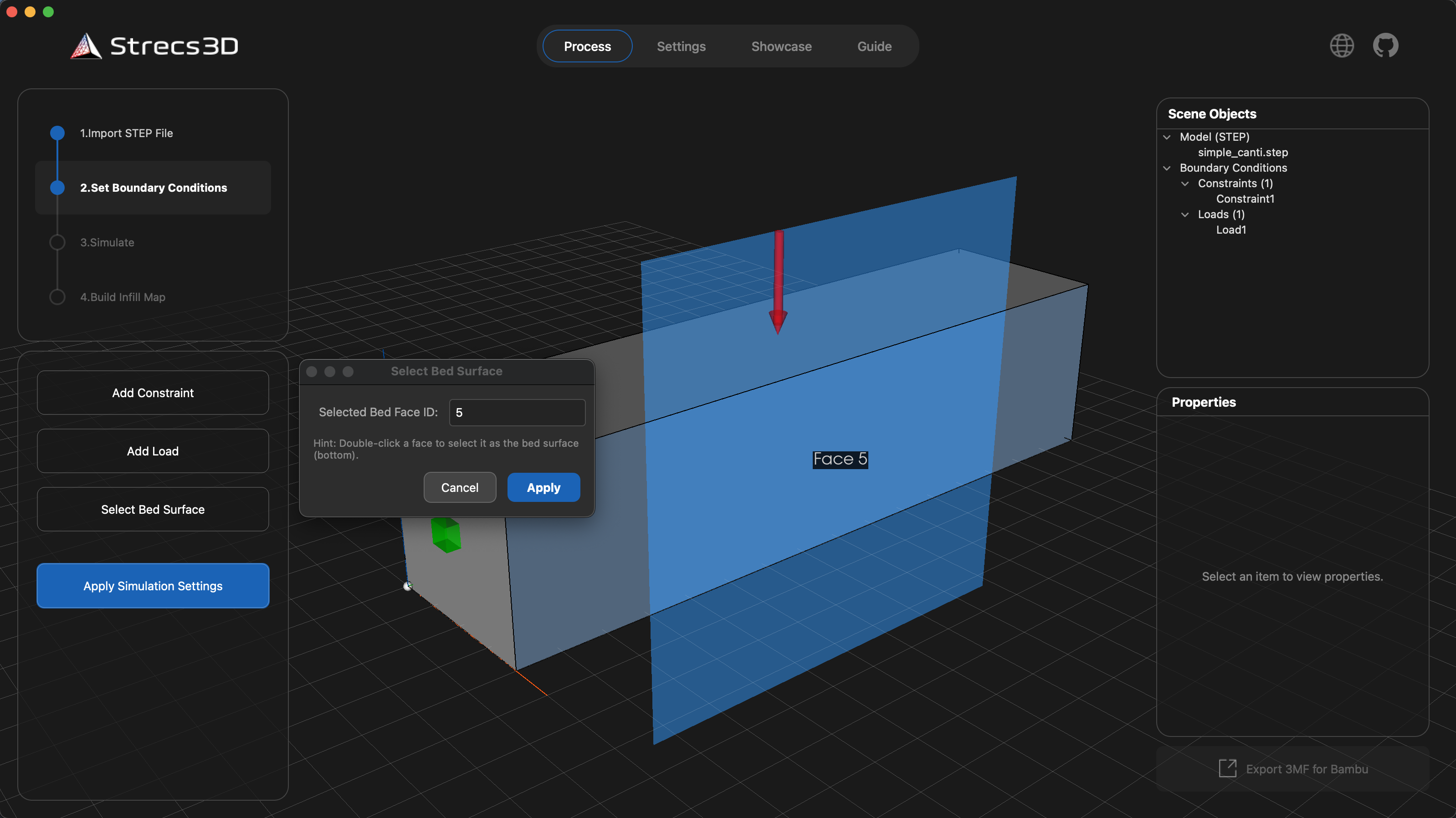
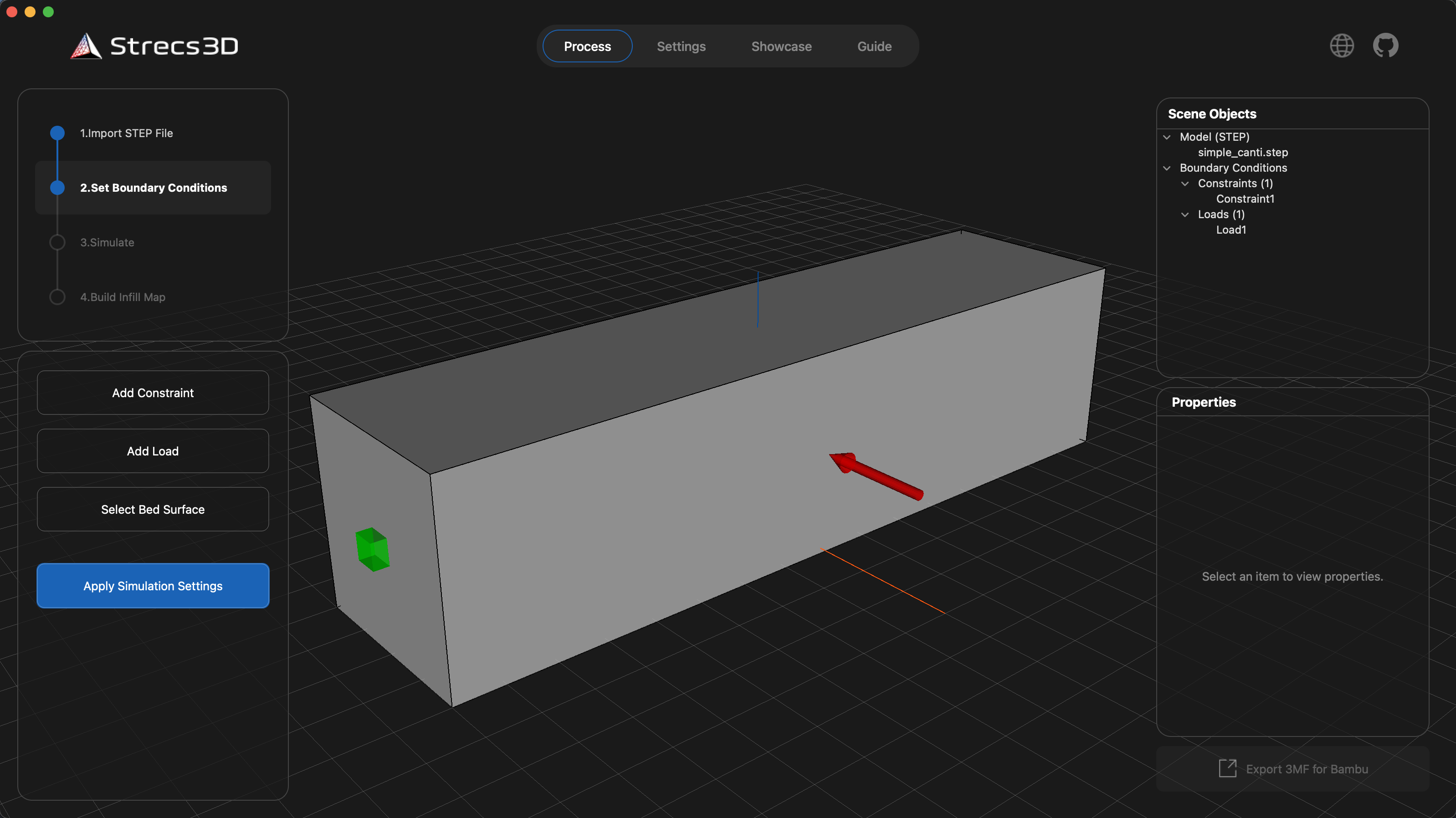
Once all settings are configured, click Apply Simulation Settings to confirm.
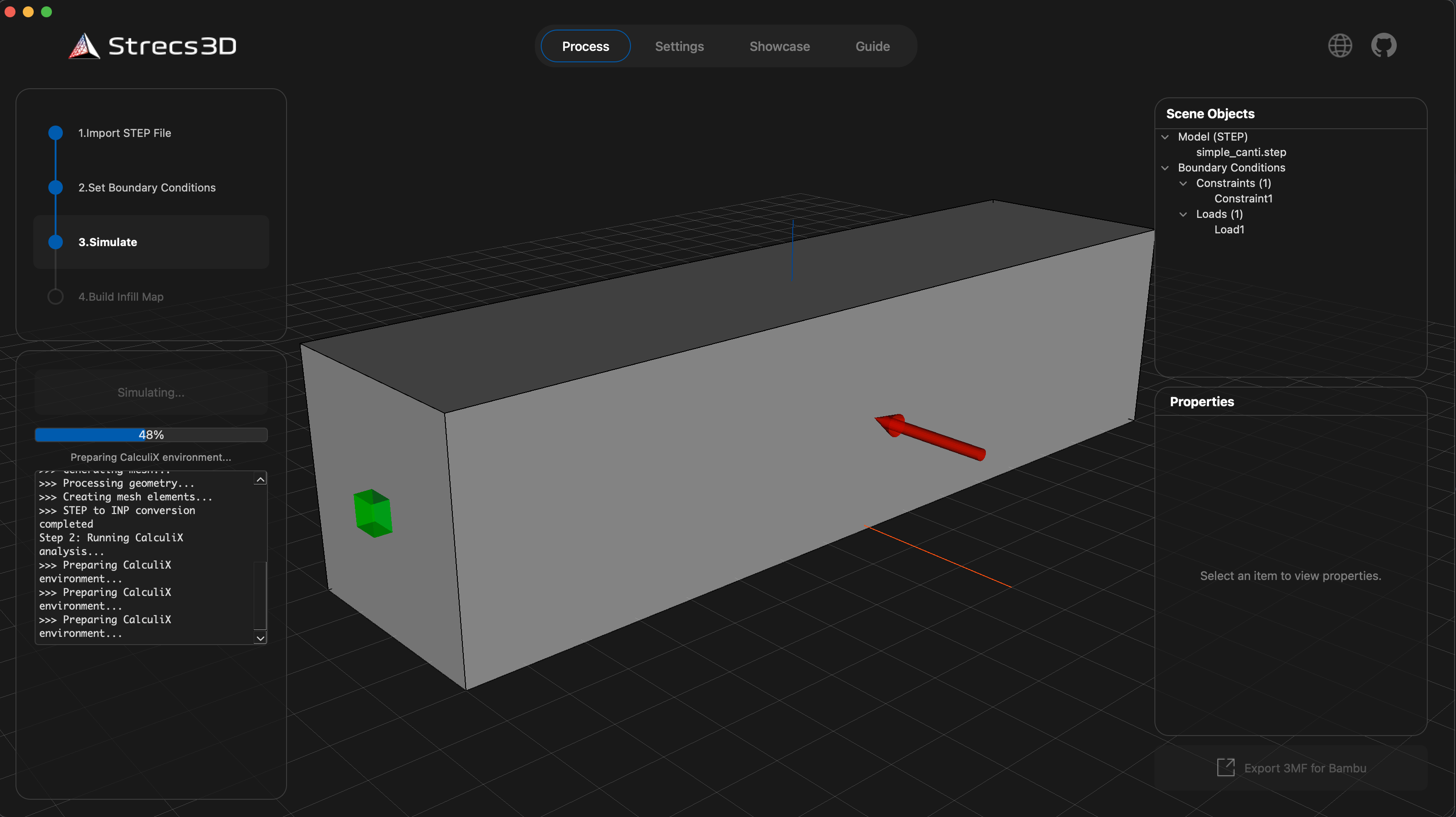
3. Running the Simulation
Click the Simulation button to start the analysis. When finished, the stress distribution will be visualized on the model.
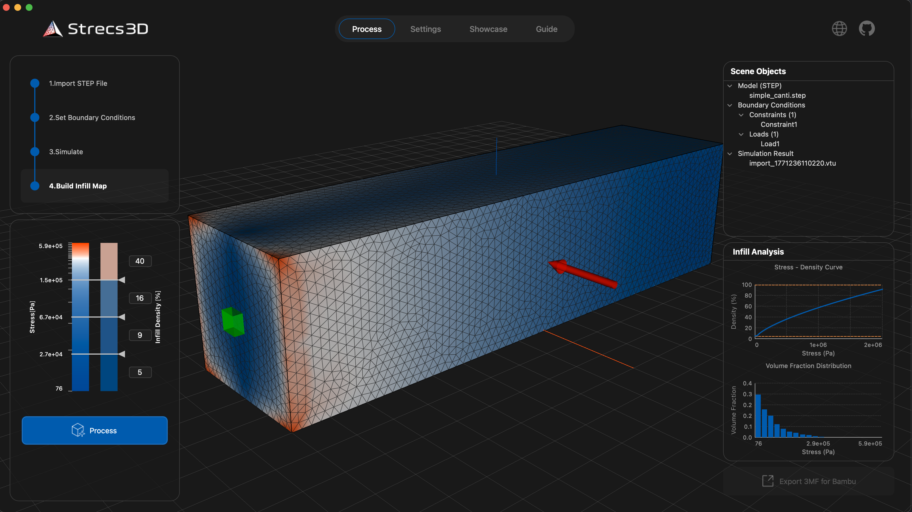
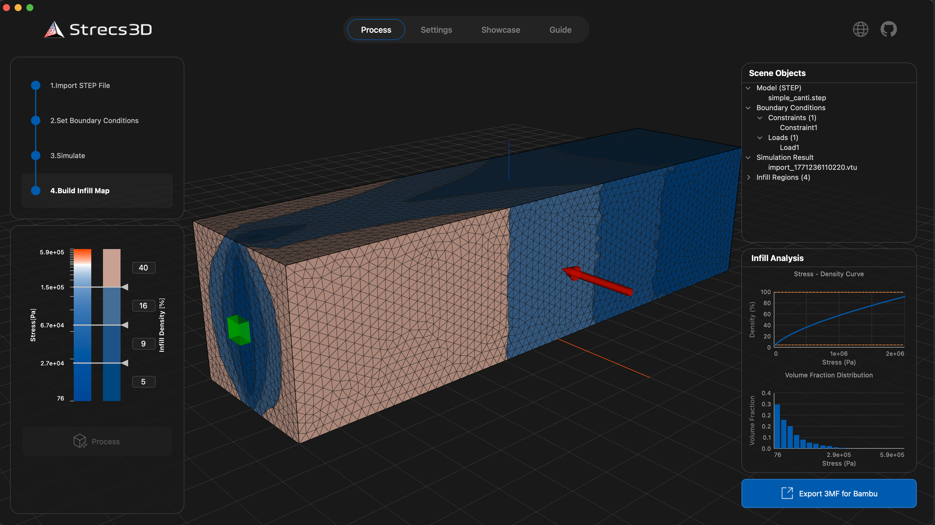
4. Generating and Exporting the Infill Map
Based on the simulation results, click the Process button to generate the infill map.
- Adjusting Density: Use the slider on the left to adjust the relationship (threshold) between stress and infill density. By default, Strecs3D divides the model into four regions and calculates the optimal density for each.
- Exporting: Once processing is complete, export the 3MF file using the button in the bottom right. This file contains both the geometry and the density information for each region.
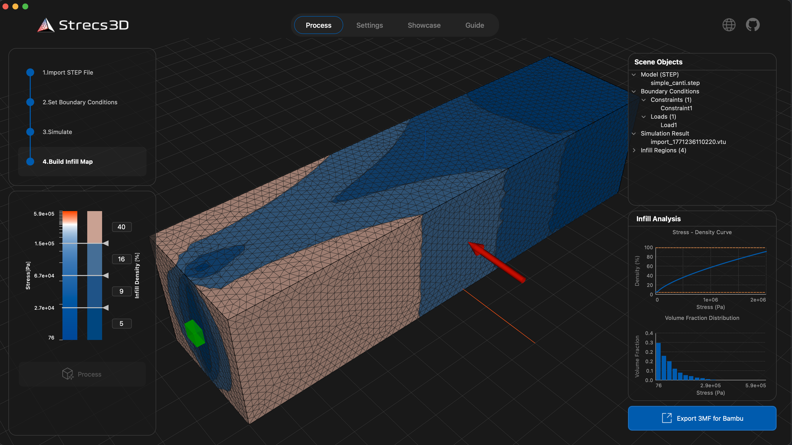
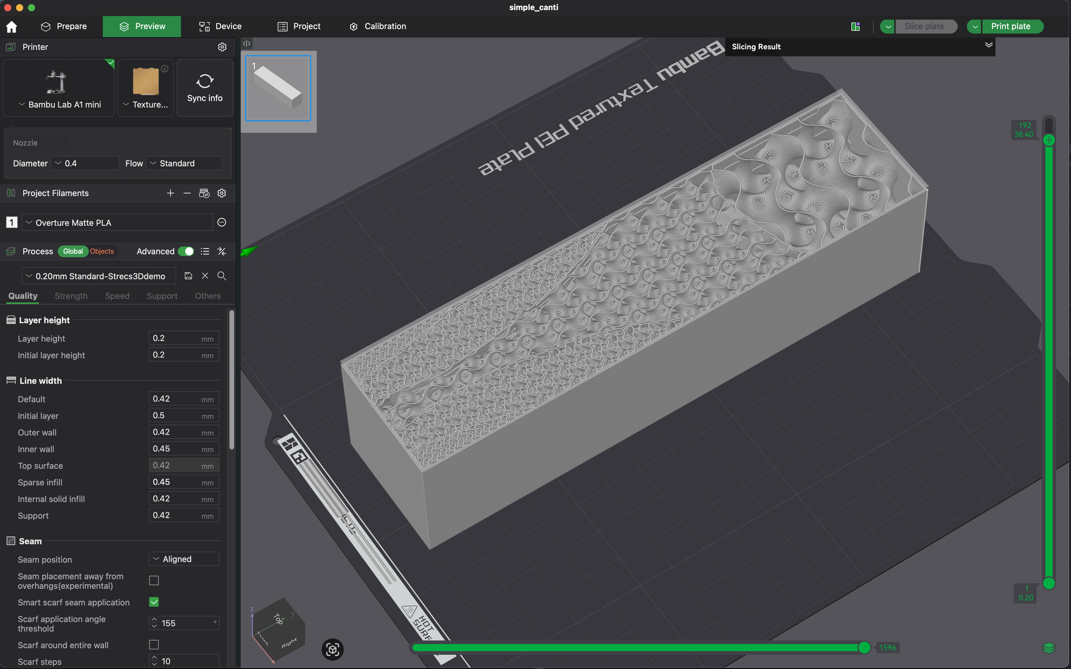
Finally, open the exported 3MF file in your preferred slicer. Start the print, and the slicer will automatically generate optimized infill in the necessary areas.
Configuration Settings
Strecs3D offers several settings for more granular control.
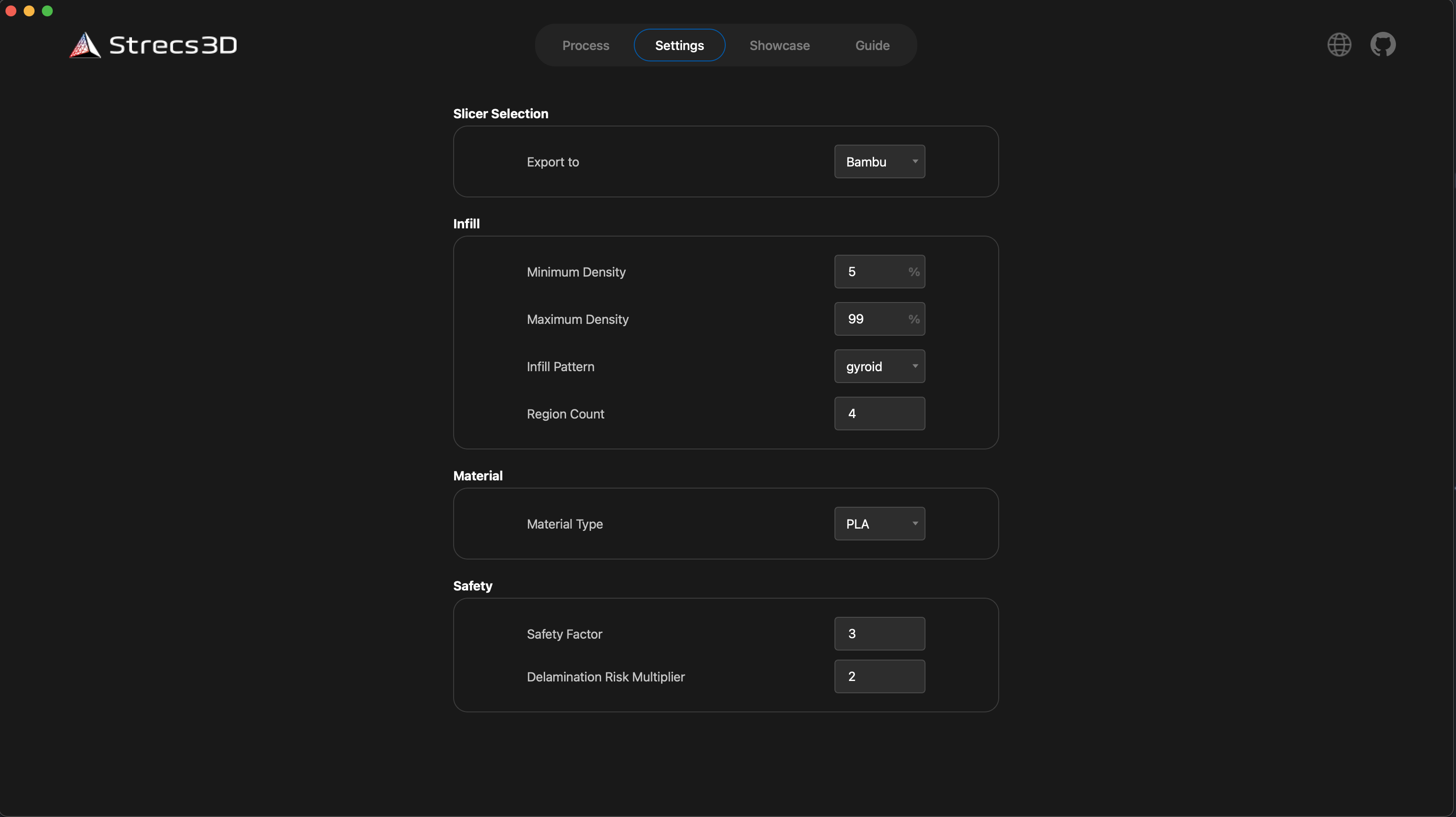
Slicer Type
- Slicer Type: The default is Bambu, but it also supports Ultimaker Cura and PrusaSlicer. Since 3MF compatibility varies between slicers, ensure you select the one you intend to use.
- Compatibility: Use "Bambu" mode for OrcaSlicer and "Prusa" mode for QiDiStudio.
Infill Settings
- Infill Density (Min/Max): Specify the minimum and maximum infill density calculated from the stress.
- Infill Pattern: We recommend using Gyroid infill for its isotropic properties.
- Region Count: The number of regions the model is divided into.
Material and Safety
- Material: Currently, PLA and ABS are available. These values are used for physical properties during analysis.
- Safety Factor: A coefficient used to calculate the required density for structural safety.
- Delamination Risk Coefficient: A coefficient that accounts for the risk of layer separation unique to 3D printing, providing extra margin against forces in the delamination direction.
Conclusion
This concludes the basic guide for Strecs3D v2.0.0. I have many more updates planned for the future.
Stay updated by following me on X (formerly Twitter):
- Developer X: @tamutamu3D
- Hashtag: #Strecs3D
- GitHub: https://github.com/tomohiron907/Strecs3D
If you create any parts using Strecs3D, please post them with the hashtag! It’s a huge motivation for development.